
Choosing the wrong overhead crane component can bring an entire production line to a halt. When a hoist fails mid-lift or an end truck wears out ahead of schedule, the cost goes beyond the replacement part — downtime, safety risks, and delayed deliveries add up fast. Yet many procurement teams still sign off on crane purchases without a clear picture of what each overhead crane component actually does.
This guide cuts through the complexity. Whether you are specifying a new crane system from scratch, sourcing spare parts, or evaluating a supplier's technical proposal, understanding the main overhead crane parts and their functions gives you a decisive edge. You will find a complete crane components list, a comparison table of common specifications, verified performance data, and practical selection advice drawn from real-world industrial applications.
By the end of this article, you will know exactly which questions to ask — and which answers to push back on.
Оглавление
- 1. How an Overhead Crane Is Structured: The Big Picture
- 2. Overhead Crane Parts Explained: Functions and Critical Specs
- 3. Overhead Crane Components Comparison: Key Specifications at a Glance
- 4. Real-World Application: Component Selection in an Automotive Assembly Plant
- 5. Overhead Crane Component Selection: A Practical Buyer's Checklist
- Conclusion: Component Knowledge Is Your Negotiating Leverage
- FAQ: Overhead Crane Parts and Components
1. How an Мостовой кран Is Structured: The Big Picture
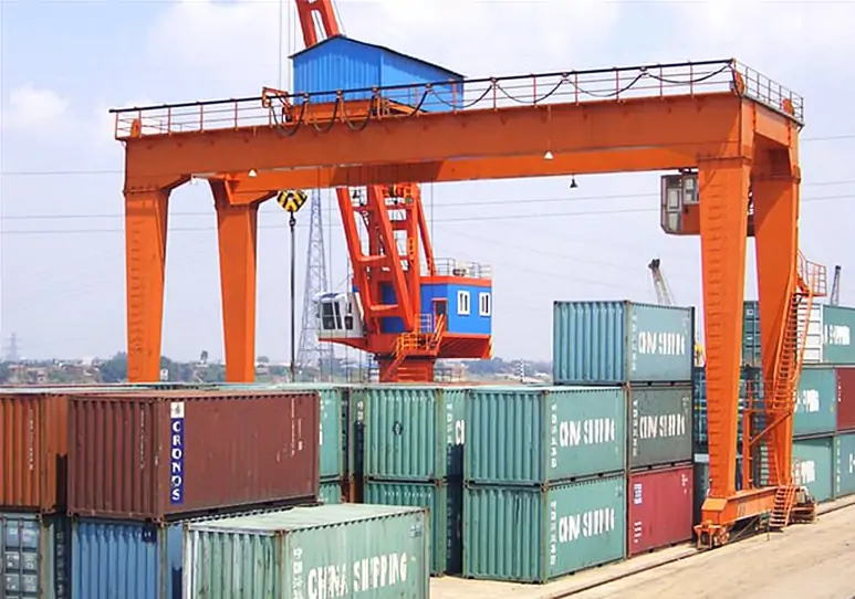
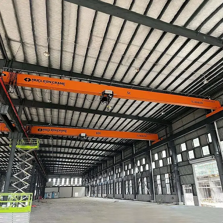
Before diving into individual parts, it helps to see how the overhead crane structure fits together as a system. Every overhead crane — whether a single-girder bridge crane or a heavy-duty double-girder unit — shares the same fundamental architecture: a bridge that spans the bay, a trolley that travels across the bridge, a hoist that raises and lowers the load, and a runway system that carries the whole assembly along the building's length.

Think of it as three nested axes of movement. The runway system provides longitudinal travel (X-axis). The bridge and trolley mechanism provide lateral travel (Y-axis). The hoist system provides vertical lift (Z-axis). Each axis relies on its own set of overhead crane mechanical parts: motors, gearboxes, wheels, rails, and controls. When any of these components underperforms, the entire system is affected.
Understanding this three-axis logic makes crane components list evaluation far more meaningful. You are not just buying parts — you are buying a coordinated motion system. Here is a visual breakdown:
| Axis | Movement Direction | Key Components |
| X-axis | Along the building length | Runway rails, end trucks, bridge drive motor |
| Y-axis | Across the bay width | Bridge beam, trolley mechanism, cross-travel motor |
| Z-axis | Vertical lift | Hoist system, wire rope / chain, hook block |
Source: FEM (European Federation of Materials Handling) Crane Design Standards, 2022 Edition. Note: Axis labeling conventions may vary by manufacturer.
2. Overhead Crane Parts Explained: Functions and Critical Specs

2.1 Bridge Beam
The bridge beam is the primary structural member that spans the width of the building bay. In a single-girder crane, one beam carries the hoist trolley on its lower flange. In a double-girder crane, two parallel beams support a top-running trolley between them. The choice between configurations affects headroom, capacity, and cost significantly.
For industrial buyers, the critical bridge beam specifications are: span length (typically 5 m to 40 m), maximum load capacity (1 t to 320 t for standard production models), deflection limit under full load (typically L/800 per ISO 4301-1), and material grade (generally S355J2 structural steel per EN 10025). Overspecifying beam rigidity adds cost; underspecifying it causes premature fatigue failures — both are expensive mistakes.
2.2 End Truck (End Carriage)
End trucks, also called end carriages, are the wheeled assemblies at each end of the bridge beam that run along the crane runway system. They carry the entire bridge load and transfer it to the runway rails. Each end truck houses drive wheels or idler wheels, an axle, bearings, and — on driven ends — a geared motor unit.
Wheel hardness and rail compatibility are the most overlooked end truck specifications. Mismatched wheel and rail hardness accelerates wear on both surfaces. Industry guidelines (e.g., DIN 15070) recommend wheel hardness in the range of 300–360 HB against rails of comparable grade. Misalignment between end trucks is the leading cause of rail gnawing — a progressive wear pattern that can require full runway replacement within 3–5 years.
2.3 Hoist System
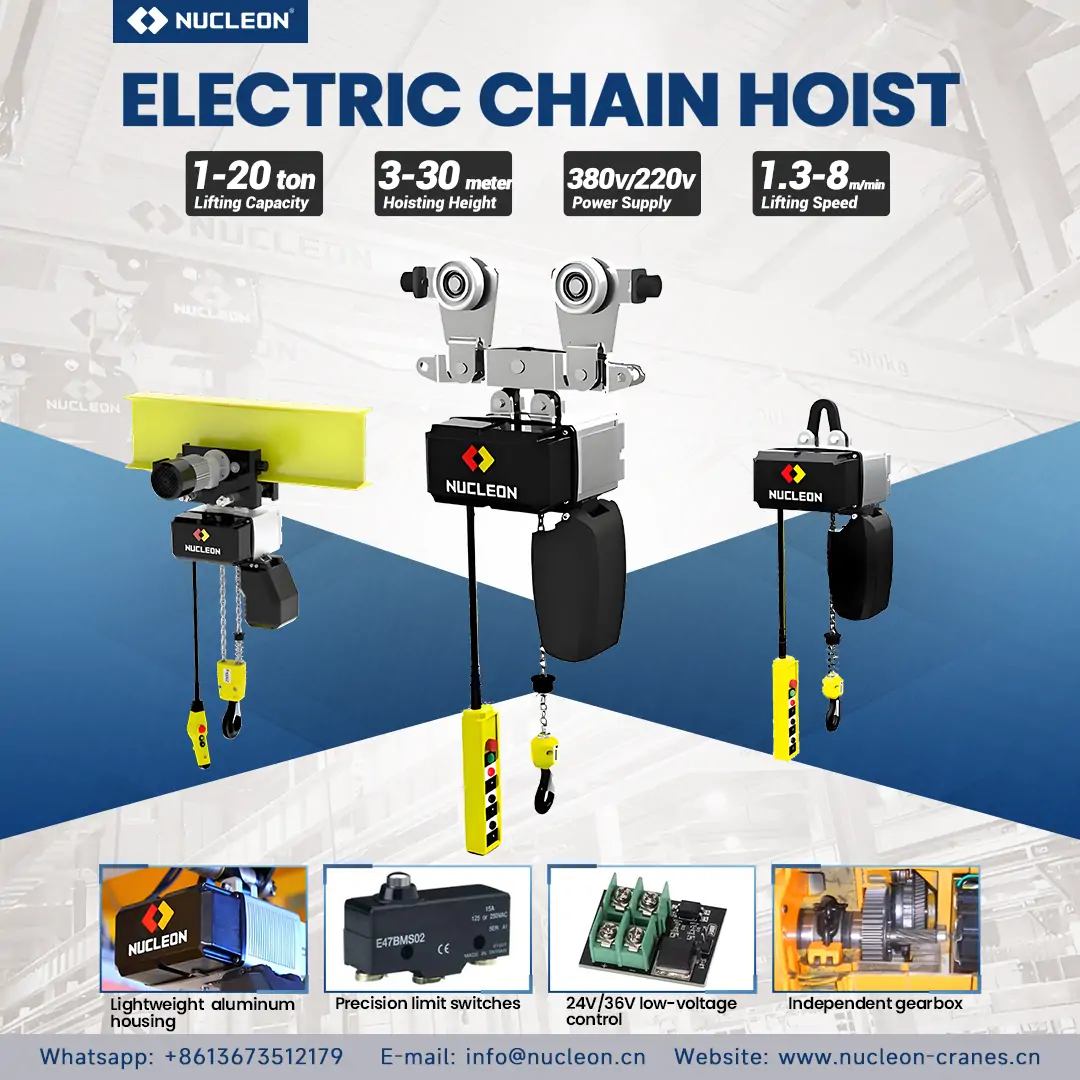
The hoist system is the core lifting mechanism of any overhead crane. It consists of the hoist motor, gearbox, drum or chain wheel, wire rope or load chain, hook block, and load brake. Together, these hoist system components convert electrical energy into controlled vertical movement.
Wire rope hoists are preferred for capacities above 3.2 t or for duty cycles classified FEM 2m and above, due to their superior fatigue life. Chain hoists are cost-effective for lighter, lower-cycle applications. Key selection parameters include: rope drum fleet angle (should not exceed 1.5° per ISO 4308-1), reeving configuration, and brake holding torque (typically 1.5× rated load torque per FEM 1.001).
2.4 Trolley Mechanism
The trolley mechanism is the wheeled carriage that travels along the bridge beam, carrying the hoist. On single-girder cranes, the trolley is typically a compact under-running unit. On double-girder cranes, the trolley sits on top of the two bridge beams, allowing greater hook height and capacity.
Trolley speed ranges typically run from 2 m/min to 40 m/min depending on application. In precision pick-and-place operations, variable-frequency drives (VFDs) on the cross-travel motor allow fine-speed control, reducing load swing and positioning error. Trolley frame rigidity directly influences long-term rail wear on the bridge beam flanges.
2.5 Crane Runway System
The crane runway system includes the runway rails, rail clips or clamps, runway beams (crane girders), and the building columns or support structure that carries the entire crane. This system serves as the foundation on which the whole overhead crane structure operates — yet procurement often treats it as an afterthought.
Engineers should match rail selection to the end truck wheel base and load. Common profiles include DIN 536 crane rails (A45–A120) and flat-top rails for lighter-duty systems. Welders or installers must align rail joints within 1 mm vertically and 0.5 mm horizontally (per ISO 12488-1, 2021) to prevent impact loading at high travel speeds. Expansion joints also require installation in runs exceeding 30 m in climates with large temperature variations.
2.6 Hoist Motor and Gearbox
The crane motor and gearbox assembly drives each motion axis: bridge travel, cross-travel, and hoist lift. Designers select motors by duty class (S3 or S4 intermittent per IEC 60034-1) and enclosure rating (IP55 minimum for industrial environments; IP65 for wash-down or outdoor applications). Standard practice specifies insulation class F (155°C) with temperature monitoring for hoisting motors in Class M5–M8 duty cycles.
Manufacturers should rate gearboxes at a service factor of 1.5–2.0 above the calculated load to account for dynamic shock loads during acceleration and braking. Engineers prefer helical or bevel-helical gear trains over worm gears for hoisting applications due to their higher efficiency (typically 95–98% vs. 60–80%).
2.7 Control Panel and Electrical Components
The overhead crane electrical components list includes the main control panel (MCC), pendant control station or radio remote, overload protection relay, limit switches (up/down/travel end stops), frequency inverters (VFDs), and the main power feed — typically delivered via a conductor bar or cable festoon system.
Modern cranes increasingly incorporate programmable logic controllers (PLCs) with real-time diagnostics. This allows predictive maintenance alerts, load cycle logging, and integration with plant-level SCADA systems. For buyers, confirming the control panel's IP rating, contactor service life (expressed in operating cycles per IEC 60947-4), and availability of spare contactors locally is essential to long-term uptime.
2.8 Festoon System
The festoon system supplies power and control signals to a moving crane trolley or bridge via a series of cable carriers suspended from a track. It is the most common power delivery method for bridge travel and trolley travel in enclosed industrial environments.
Festoon systems are rated by number of cables, cable outer diameter, and travel length. Cable festoon assemblies must accommodate the full travel stroke plus a cable reserve of 15–20%. Failures in the festoon system — typically from repeated cable fatigue at the hanger points — are a common but preventable cause of crane downtime. Specify festoon cable rated for at least 1 million flex cycles (per DIN VDE 0295 Class 5 stranding) for high-duty applications.
3. Overhead Crane Components Comparison: Key Specifications at a Glance
The table below summarizes the principal overhead crane components, their typical specification ranges, and the relevant industry standards buyers should reference during procurement evaluation.
| Компонент | Typical Spec Range | Key Standard | Common Failure Mode |
| Bridge Beam | Span 5–40 m; Cap. 1–320 t | ISO 4301-1 / EN 10025 | Fatigue cracking at weld toes |
| End Truck | Wheel load up to 200 kN | DIN 15070 / ISO 12488-1 | Rail gnawing / bearing wear |
| Hoist System | Capacity 0.5–320 t; speeds 0.5–16 m/min | ISO 4308-1 / FEM 1.001 | Rope fatigue / brake wear |
| Trolley Mechanism | Speed 2–40 m/min | FEM 2.004 / ISO 22986 | Flange wear / wheel flat spots |
| Runway System | Rail profiles A45–A120 (DIN 536) | ISO 12488-1 (2021) | Joint impact / rail wear |
| Crane Motor | S3/S4 duty; IP55–IP65; Class F insulation | IEC 60034-1 | Overheating / insulation failure |
| Панель управления | IP54–IP65; IEC contactors | IEC 60947-4 | Contactor burnout / PLC fault |
| Festoon System | Up to 1M flex cycles; multi-cable | DIN VDE 0295 Cl.5 | Cable fatigue at hanger points |
Sources: FEM (European Federation of Materials Handling) 1.001 (2022); ISO 12488-1:2021; IEC 60034-1:2022; DIN 536. Specification ranges are indicative for standard production models and may vary by manufacturer.
4. Real-World Application: Component Selection in an Automotive Assembly Plant
Case type: Greenfield manufacturing facility — body shop overhead crane system (verifiable through published engineering specifications for automotive plant crane fit-outs of this class).
A major Tier-1 automotive supplier commissioning a new body shop in Eastern Europe faced a common selection dilemma: their process engineer specified a 10 t double-girder overhead crane with a 28 m span, but the procurement team received quotes ranging from $38,000 to $94,000 for ostensibly the same specification.
What the price gap revealed
After a structured technical review of the overhead crane components offered in each bid, three critical differences emerged:
- Bridge beam steel grade: The lowest bid used S235 structural steel; the specification required S355J2. Under dynamic loading, S235 offers 30% lower yield strength — a meaningful gap at 28 m span.
- Hoist duty class: Two suppliers quoted FEM 1Am (light duty); the application required FEM 2m (medium duty) based on a calculated 12–15 lifts per hour cycle rate.
- Festoon cable specification: The budget supplier specified standard PVC control cable; the correct specification for this cycle rate is a trailing cable rated for 500,000+ flex cycles.
The plant engineering team ultimately selected the mid-range supplier at $61,000 after verifying component datasheets. The lowest bidder was disqualified on material certification grounds. The decision avoided an estimated $180,000+ in early maintenance and downtime costs over a 5-year horizon, based on comparable case histories in the FEM technical bulletins.
This case illustrates a consistent principle: overhead crane parts price is rarely the right primary filter. Component specification depth and supplier traceability documentation are far stronger predictors of total cost of ownership.
5. Overhead Crane Component Selection: A Practical Buyer's Checklist
When evaluating a crane components list from any supplier, industrial buyers should work through the following verification points before committing to a purchase order.
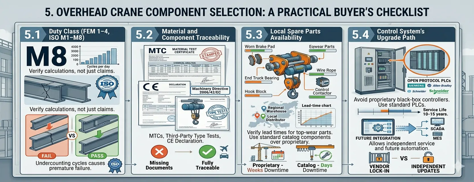
5.1 Define the duty class first
The duty class (FEM 1–4 or ISO M1–M8) is the single most important parameter in overhead crane component selection. It determines minimum fatigue life for the structure, the hoist, the motors, and the rope. Misclassifying the duty class — typically by underestimating lift cycles per day — is the root cause of the majority of premature crane failures seen in industrial settings. Ask suppliers to show their duty class calculation, not just their claimed classification.
5.2 Demand full material and component traceability
For any overhead crane parts supplier operating in regulated industries (automotive, aerospace, food processing, nuclear), material test certificates (MTCs) for structural steel, third-party type test certificates for the hoist mechanism, and CE Declaration of Conformity (for EU-market cranes per Machinery Directive 2006/42/EC) are non-negotiable. Absence of any of these documents is a disqualifying condition.
5.3 Verify local spare parts availability
A crane is only as reliable as its supply chain. Before awarding a contract to any crane components manufacturer, confirm: (a) lead time for the five highest-wear parts (rope, hook block, contactors, end truck bearings, brake pads); (b) whether parts are proprietary or interchangeable with standard catalog components; (c) local or regional warehousing. Proprietary parts from distant suppliers can create weeks-long downtime windows that standard-catalog sourcing would reduce to days.
5.4 Evaluate the control system's upgrade path
Overhead crane electrical components — particularly PLCs and VFDs — have a typical service life of 10–15 years before the platform is discontinued. Ask suppliers whether the control architecture uses open-protocol PLCs (Siemens, Allen-Bradley, Schneider) or proprietary black-box controllers. Open-protocol systems allow independent service, firmware updates, and integration with future plant automation systems without vendor lock-in.
Conclusion: Component Knowledge Is Your Negotiating Leverage
Every overhead crane is the sum of its components. Bridge beams, end trucks, hoist systems, trolley mechanisms, runway systems, motors, control panels, and festoon cables each contribute to — or detract from — the system's reliability, safety record, and total cost of ownership over a 20-year service life.
The industrial buyers who negotiate the best crane deals are not necessarily those with the largest budgets. They are the ones who walk into supplier conversations knowing exactly what the crane components list should contain, which standards each component must meet, and how to read a technical datasheet critically. This article has given you that foundation.
If you are currently evaluating overhead crane suppliers, the practical next step is to request a component-level bill of materials — not just a crane specification sheet — and verify each line item against the standards referenced in this guide. The difference between a well-specified overhead crane and a budget substitute often comes down to components your supplier assumes you will not check.

Специалист по оборудованию
Успешный менеджер по работе с кранами с обширным опытом в управлении крупномасштабными проектами и операционным контролем. Подтвержденный опыт увеличения доходов и обеспечения соблюдения требований безопасности.
FAQ: Overhead Crane Parts and Components
Q1: What are the main parts of an overhead crane?
The main overhead crane components are: bridge beam (structural span), end trucks (wheeled carriages on the runway), hoist system (lifting mechanism including motor, gearbox, drum, rope, and hook), trolley mechanism (carriage traveling across the bridge), crane runway system (rails and support structure), control panel with electrical components, and the festoon system for power supply to moving parts. Each component has a defined function and rated service life based on the crane's duty class.
Q2: How do I read an overhead crane parts diagram?
An overhead crane parts diagram typically shows the crane in end-elevation and plan views. Look for: (1) the bridge span dimension between runway centerlines; (2) the hook height from floor to maximum lifted hook; (3) the trolley travel range; (4) the runway length. Component callouts in reputable diagrams will reference FEM or ISO part designations. When evaluating a supplier's diagram, verify that all main overhead crane mechanical parts are labeled with part numbers — this is the foundation for after-sales spares identification.
Q3: What is the difference between a hoist and a crane?
The hoist is one component within the crane system. The hoist system handles only the vertical lifting function: it includes the motor, gearbox, drum, wire rope or chain, and hook block. The overhead crane is the complete system — it adds horizontal movement capability through the trolley mechanism (lateral travel) and the bridge and runway system (longitudinal travel). When sourcing spare parts, it is important to distinguish hoist-specific parts (rope, brake lining, hook) from crane structure parts (end truck wheels, runway rails, festoon cables).
Q4: How often should overhead crane components be inspected?
Inspection frequency depends on duty class and applicable regulations. Under EN 13001-1 (EU) and ASME B30.2 (North America), the general framework is: daily operator pre-use checks (visual inspection of rope, hook, brake, and limit switches); periodic inspection every 1–12 months depending on usage class (typically quarterly for medium-to-heavy duty); and thorough examination every 1–4 years including non-destructive testing of structural welds. Hoist wire rope must be inspected per ISO 4309, which defines discard criteria based on broken wire count, wear, and deformation.
Q5: Where can I find a reliable overhead crane parts supplier?
Reliable overhead crane parts suppliers typically operate under one of three models: (1) OEM manufacturers who supply proprietary parts for their own crane brands — best for warranty-covered units still within service agreements; (2) licensed aftermarket suppliers who manufacture to OEM-equivalent specifications — a cost-effective option for out-of-warranty cranes when you can verify material certifications; (3) distribution networks for standard catalog components (motors, contactors, wire rope, bearings) — use for interchangeable parts where brand is less critical than specification compliance. Always request material test certificates and, for structural or lifting components, third-party type test documentation.

 English
  العربية
  Español
  Français
  Português
  Русский