

If you are selecting or operating a jib crane, knowing its parts is not optional — it is essential. The wrong component choice or a missed maintenance point can lead to costly downtime or, worse, a safety incident. This guide breaks down every major part of a jib crane, explains its function, and tells you what to look for when evaluating a unit.
Whether you are a plant engineer specifying new equipment or a maintenance technician troubleshooting a unit, this article gives you the component-level knowledge you need. By the end, you will be able to read a jib crane specification sheet with confidence, ask the right questions before you buy, and know exactly which parts require the closest inspection over time.
The Core Structure — Load-Bearing Parts of a Jib Crane
These are the structural elements that define a jib crane's capacity and reach. Getting them right at the selection stage determines everything else.
Mast (Vertical Column)
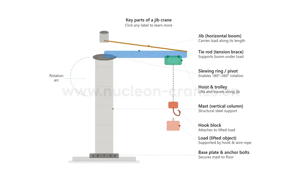
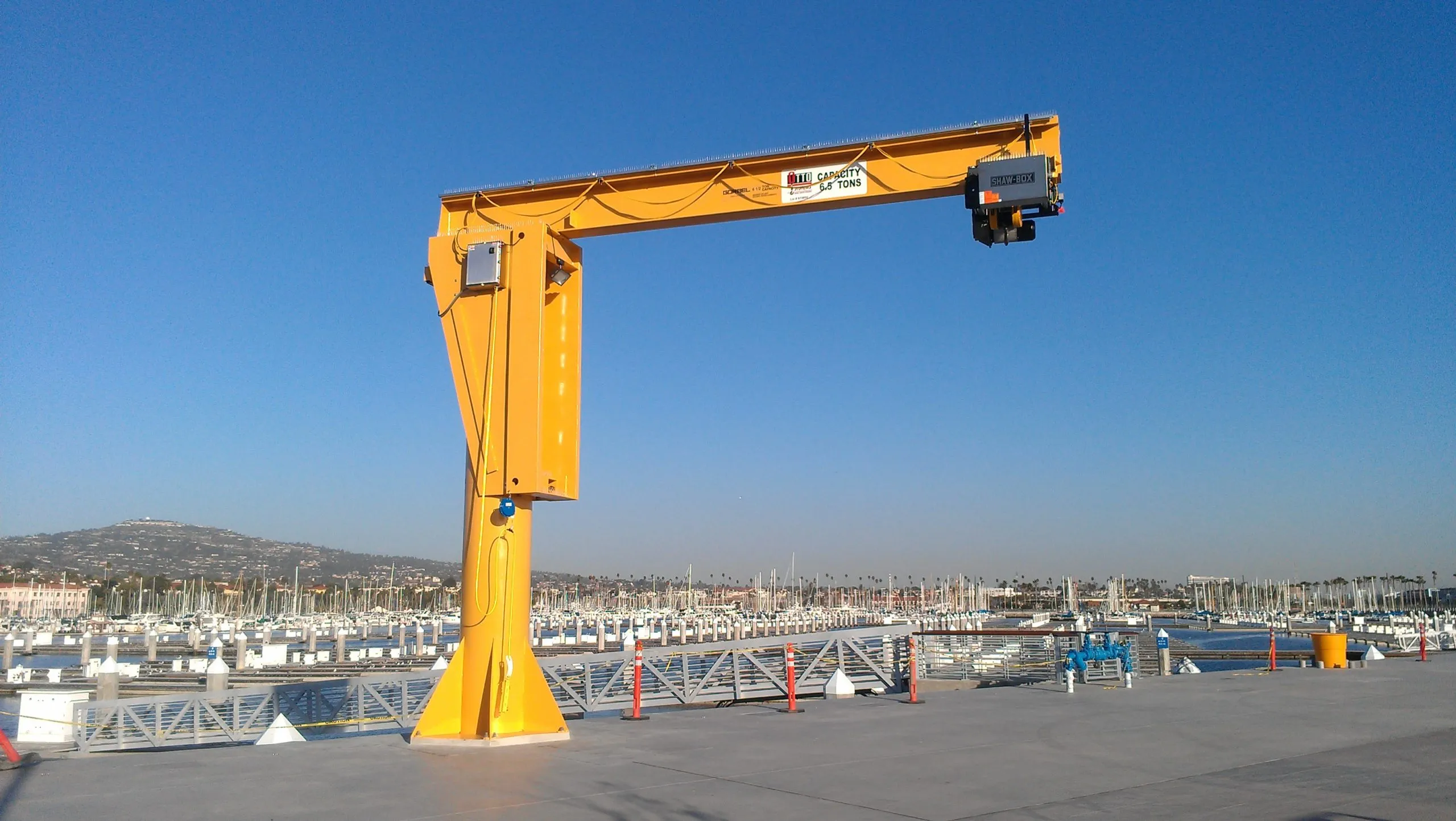
The mast is the backbone of the crane. It is a vertical steel column — usually hollow square or round section — anchored to the floor or wall. All other components transfer their loads back to the mast.
Standard mast heights range from 3 m to 6 m for floor-mounted units, though custom heights are available. Wall-mounted jib cranes use a shorter stub mast attached to a structural wall. The mast must be sized for both the rated load and the bending moment created by the jib arm's reach. Undersizing the mast is the most common structural error in jib crane installations.
Key specification: always request the mast's moment of inertia data and confirm it matches the manufacturer's load chart.
Base Plate and Anchor Bolts
The base plate connects the mast to the floor. It distributes the crane's load across a wider area and serves as the anchoring point for the hold-down bolts. Most manufacturers supply a pre-drilled steel plate, typically 20–30 mm thick, with a bolt circle pattern that matches the mast flange.
Anchor bolt sizing follows ISO 4014 or equivalent standards. Minimum concrete slab depth for standard installations is typically 250–300 mm, reinforced. Insufficient slab thickness is a frequently overlooked installation failure point. Always verify the concrete specification against the crane manufacturer's foundation requirement sheet before pouring.
Jib (Horizontal Boom)
The jib is the horizontal arm that carries the load. It extends outward from the mast and defines the crane's working radius. Most jibs are fabricated from I-beam or box-section steel. Standard reach ranges from 1.5 m to 6 m, with heavier-duty units offering up to 12 m.
The jib carries bending loads along its length as the hoist travels. This is why the profile of the jib section matters: a deeper I-beam resists deflection better than a shallow one at the same weight. Excessive deflection under load is a sign the jib section is undersized for the span.
Tie Rod (Tension Brace)
The tie rod runs diagonally from the top of the mast down to the outer end of the jib. It works in tension, counteracting the downward bending force the load places on the jib. Without the tie rod, the jib would deflect heavily under load.
Tie rods are typically solid round bar or threaded rod with turnbuckles that allow tension adjustment during installation. In some designs — particularly underhung jib cranes — the tie rod is replaced by a structural bracket welded directly to the mast. Regular inspection of the tie rod connection pins and any threaded fasteners is essential. Fretting corrosion at the pin holes is a common wear point.
The Rotation System — How a Jib Crane Swings
Slewing Ring and Pivot Mechanism
The slewing ring is what allows the jib to rotate around the mast. It is a large-diameter bearing — either a plain bush bearing or a rolling-element slewing ring — mounted at the top and sometimes also at the base of the mast. The jib assembly attaches to the inner or outer race of this bearing.
Jib cranes typically rotate through 180°, 270°, or 360° depending on the mounting configuration and the slewing ring type. Floor-mounted freestanding units commonly achieve 360° rotation. Wall-mounted units are limited by the wall itself, usually to 180° or 270°.
The slewing ring must be lubricated at regular intervals — typically every 250 operating hours per ISO 9283 guidance. Neglected lubrication causes premature wear and increases the torque required to rotate the crane, which in turn strains the drive system.
Manual vs. Motorized Slewing
Smaller jib cranes — typically under 500 kg capacity — are often rotated manually by the operator pushing the jib. Larger units use an electric slewing motor connected to a ring gear on the mast, controlled from a pendant station.
Motorized slewing should include a soft-start mechanism to prevent abrupt load swing. Variable frequency drives (VFDs) are the current standard for achieving smooth acceleration and deceleration. If a crane's motorized slew does not include VFD control, the inertia forces generated at start and stop can exceed the crane's rated dynamic load.
The Lifting System — Hoist, Trolley, and Hook
Electric Chain Hoist or Wire Rope Hoist
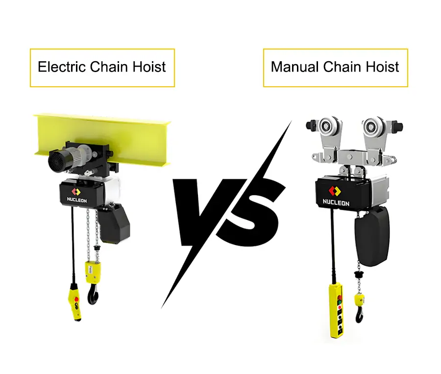
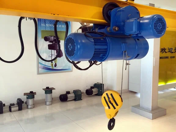
The hoist is the power unit that raises and lowers the load. Two types are common on jib cranes:
| Característica | Polipasto eléctrico de cadena | Polipasto de cable de acero |
| Capacidad típica | Up to 5,000 kg | Up to 80,000 kg and beyond |
| Headroom requirement | Higher (chain bag) | Lower (compact drum) |
| Duty class | FEM 1Am–3m | FEM 2m–5m |
| Maintenance interval | Every 6–12 months | Every 6–12 months |
| Ideal application | Light/medium duty | Heavy/continuous duty |
FEM (Fédération Européenne de la Manutention) duty classes define how intensively a hoist can be used. Matching the duty class to the actual cycle rate of the application is critical — using a light-duty hoist on a high-cycle production line is a common cause of premature hoist failure.
Tranvía
The trolley carries the hoist and travels along the lower flange of the jib beam. It converts the fixed lifting point of the hoist into a variable working radius. Most trolleys use hardened steel wheels that run on the jib flange. Load eccentricity — the wheel load shifting to one side due to off-center loading — can cause flange wear if the trolley wheel gauge does not match the beam width closely.
Motorized trolleys offer push-button control of load positioning, which reduces operator fatigue and improves cycle times. Manual geared trolleys are a reliable lower-cost option for lower-frequency operations.
Hook Block and Safety Latch
The hook block is the final load attachment point. It must be rated to at least the crane's SWL (Safe Working Load) and must carry a CE marking for machines used within the European Economic Area, or EAC certification for use in Eurasian markets.
All hooks on equipment used under EN 13157 (hand-powered lifting equipment) and EN 14492-2 (power-driven hoists) must include an anti-drop safety latch. This latch prevents the rigging sling or shackle from accidentally disengaging if the load moves suddenly. Inspect the latch for spring tension and free movement at every pre-use inspection. A latch that does not spring back fully must be replaced before the crane is returned to service.
Electrical and Control Components
Pendant Control Station
The pendant is the operator's interface. It hangs from the hoist or a festoon cable system and provides pushbutton control for hoist up/down, trolley travel (if motorized), and slewing (if motorized). Modern pendants carry IP54 or IP65 ingress protection ratings for industrial environments.
A well-designed pendant includes an emergency stop mushroom button that is easily accessible and clearly identified. OSHA 1910.179 and EN 60204-32 both require emergency stop functionality on electrically powered cranes.
Festoon Cable System and Power Supply
The festoon system supplies power to the hoist as it travels along the jib. It consists of cable trolleys hanging from a steel rod or C-rail, carrying a looped electrical cable that extends and retracts as the hoist moves. Poor festoon cable routing is one of the leading causes of electrical faults on jib cranes.
The crane's power supply must match the hoist's voltage and phase requirement — typically 380–415V / 3-phase / 50 Hz in European installations. Always confirm the available fault current at the supply point against the crane's maximum current draw to ensure correct protective device sizing.
Choosing the Right Configuration — A Quick Comparison
| Configuración | Montaje | Rotación | Lo mejor para |
| Freestanding floor-mounted | Concrete slab | Up to 360° | Open floor area, full coverage |
| Wall-mounted | Structural wall | Up to 270° | Space-constrained bays |
| Mast-mounted (pillar) | Steel column | Up to 360° | Existing structural steel |
| Ceiling-mounted (underhung) | Overhead beam | Up to 360° | Low-headroom buildings |
Each configuration changes which parts carry the primary loads. A wall-mounted jib crane, for example, eliminates the base plate and floor anchor system but requires a detailed wall load assessment before installation.
Obtener cotización de soluciónSummary and Action Steps
The parts of a jib crane work as a system. A well-specified mast means nothing if the anchor foundation is undersized. A high-quality hoist delivers no value if the festoon system fails after six months. Approach jib crane selection by auditing every component against your duty cycle, environment, and regulatory requirements.
Before purchasing, request the following from your supplier: full component load calculations, CE or EAC certification documentation for the hoist and hook, the lubrication schedule for the slewing ring, and the recommended inspection intervals for the tie rod and anchor hardware.
If you are replacing components on an existing crane, always match the replacement part to the original design specification. Substituting a higher-capacity hook does not automatically make the crane safer — the weakest link in the system sets the actual SWL.

Especialista en Equipos
Gerente de Negocios de Grúas con experiencia y amplia trayectoria en gestión de proyectos de elevación pesada y supervisión operativa. Historial comprobado de impulso del crecimiento de los ingresos y garantía del cumplimiento de las normas de seguridad.
Preguntas frecuentes
1. What is the most important structural part of a jib crane?
The mast is the primary structural element. All bending moments and vertical loads from the jib and its payload transfer back through the mast to the foundation. Mast failure is rare when correctly specified, but is the most serious possible structural failure mode.
2. How far can a jib crane reach?
Standard jib cranes have a reach of 1.5 m to 6 m. Heavy-duty custom units can extend to 12 m or more, though longer jibs require proportionally larger mast sections and stronger foundations to control deflection.
3. What is the difference between a tie rod and a mast brace?
A tie rod works in tension — it is a slender rod or bar that pulls the end of the jib upward. A mast brace works in compression — it is a structural section that pushes. Most modern floor-mounted jib cranes use tie rods rather than braces because they are lighter and easier to adjust.
4. How often should the slewing ring be lubricated?
A general industry guideline, consistent with ISO 9283, is every 250 operating hours or at least once every three months, whichever comes first. High-temperature or dusty environments may require more frequent intervals. Always follow the crane manufacturer's specific lubrication specification.
5. Can a jib crane be installed without a concrete slab?
Not safely, for a freestanding floor-mounted unit. The anchor bolts must embed into adequately reinforced concrete — minimum 250 mm depth is common, though the exact specification depends on the crane's rated capacity and reach. Steel plate floors or mezzanine decks require a structural engineer's assessment before installation.

 English
  العربية
  Español
  Français
  Português
  Русский